
5W Radio With a 50W Antenna: UHF Antenna Power Rating and the 3 Red Lines That Kill Mobile Radios
author: ETMY RF Technical Team
2026-11-13
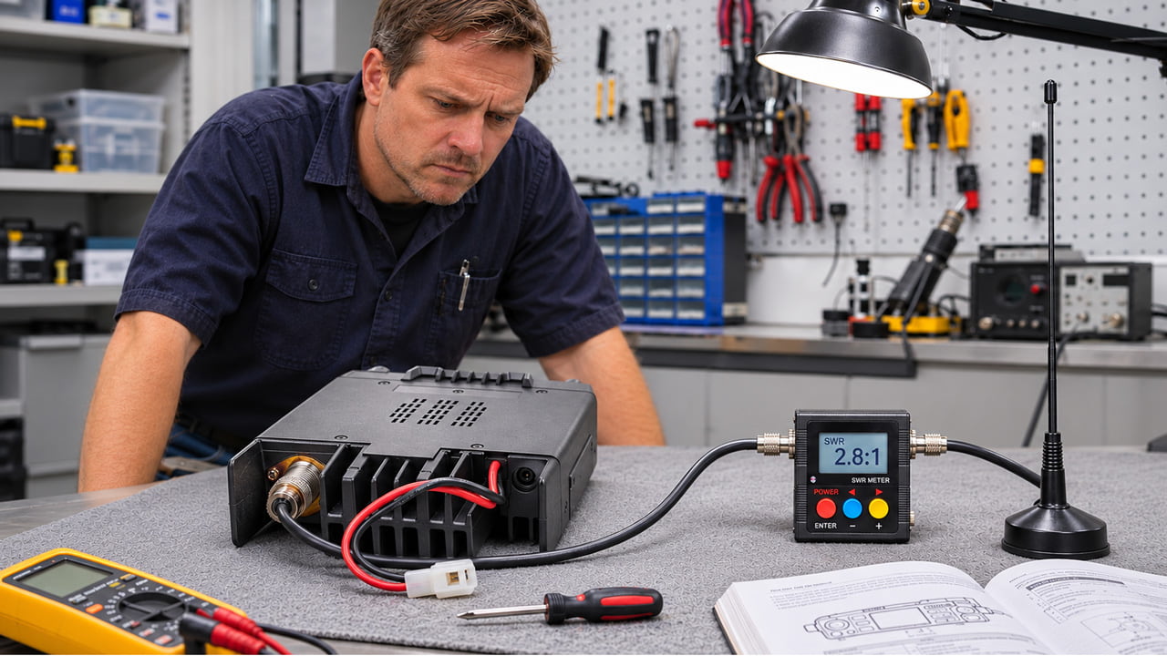
Mike spent $120 on a "50W heavy-duty" UHF antenna for his mobile radio and set the output power to 25W. A week later, upon a cold start, the unit immediately entered protection mode: the power amplifier (PA) triggered a high-temperature alarm, locking the output at a low level—and no amount of resetting could restore it to full power. When the service technician opened the unit, they discovered that the feedline connector was overheating due to a poor connection, with a standing wave ratio (SWR) of 2.8:1. This is a classic scenario that radio technicians hear all the time: "The antenna is rated for 50W—why did my radio burn out?" The answer is simple: power handling isn't determined by the antenna alone; it’s limited by the weakest link in the entire chain—the antenna, feedline, connectors, and tuning. The following three "red lines" regarding UHF antenna power are where most mobile radio PA burnout incidents actually begin.
Regulations for the UHF band focus on **EIRP (Equivalent Isotropically Radiated Power)**. The formula for determining compliance is:
EIRP (dBm) = Transmit Power (dBm) + Antenna Gain (dBi) − Feedline Loss (dB)
EIRP (dBm) = Transmit Power (dBm) + Antenna Gain (dBi) − Feedline Loss (dB)
Let’s do the math. 25W is approximately 44 dBm. If you pair this with a 5.2 dBi whip antenna and a feedline with 1 dB of loss, the EIRP reaches 48 dBm—an equivalent radiated power of about 63W. In many regions, the regulatory limit for the 400 MHz band is around 10W EIRP; this configuration far exceeds that threshold. Even with a shorter whip antenna—5W output, 2 dBi gain, and 1 dB loss—you end up at 45 dBm (approx. 31.6W), which still exceeds the limits in most jurisdictions. The premise "my radio is only 25W" is fundamentally flawed; regulators look at the total amount of power actually radiated.
The 50W or 100W rating found on a mobile radio’s nameplate refers to its continuous power-handling capacity under ideal conditions—specifically, a **1:1 SWR (Standing Wave Ratio) and excellent heat dissipation**. Real-world installation scenarios rarely, if ever, meet these criteria:
• As the SWR rises, reflected power causes repeated heating at the connector interface. A shift from an SWR of 1.5:1 to 2.8:1 can result in a temperature difference of several tens of degrees at the connector during continuous transmission.
• Power ratings often come with a caveat in the fine print: "based on a 1:1 SWR and free-space cooling." A whip antenna mounted on a vehicle roof—clamped against the car's paint and metal body—is far removed from these test conditions.
A practical rule of thumb: If a specification sheet lists a wattage without defining the SWR or cooling conditions, it is safer to assume an operational limit of 30%–50% of that figure. Even when a radio is rated for 100W, the "headroom" is limited; for example, a 144/430 MHz dual-band mobile whip antenna (like the 92cm, 5.2 dBi UHF, 50Ω, SL-16 connector-equipped AZ510FX) represents the upper limit for a 25W-class radio. If you transmit at more than 15W on a regular basis, that "headroom" is no longer a safety margin—it becomes a "thermal budget" that is being consumed.
Cases where an antenna remains intact while the radio itself fails are usually due to the following:
• The cumulative effect of feedline loss and SWR. Thin coaxial cables like RG-58 lose over 1dB of signal every 3 meters at 400 MHz. When compounded by an SWR of 2.8:1 or higher, the power amplifier (PA) is forced to push even more power to compensate, creating a vicious cycle.
• Poor or oxidized connections.** If the shielding layer is not properly secured, or if moisture enters the dielectric, it creates a point of high equivalent resistance. The resulting heat is concentrated at the connector interface, not within the antenna itself.
Methods to prevent overpower, ranked by importance:
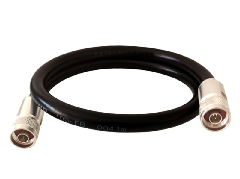
1. Never use temporary test cables for permanent mobile installations. Choose thin, high-temperature-resistant coaxial cable—such as LMR-400. LMR-400 exhibits only 3.0 dB loss per 100 ft at 400 MHz, and its bonded foil plus tinned copper braid prevents stray RF ingress between adjacent radio lines.
2. Connectors: Apply dielectric grease only to the outer shell, never to the center pin. Ensure the shielding is firmly compressed before tightening the flange—secure the shield first, then tighten the connector.
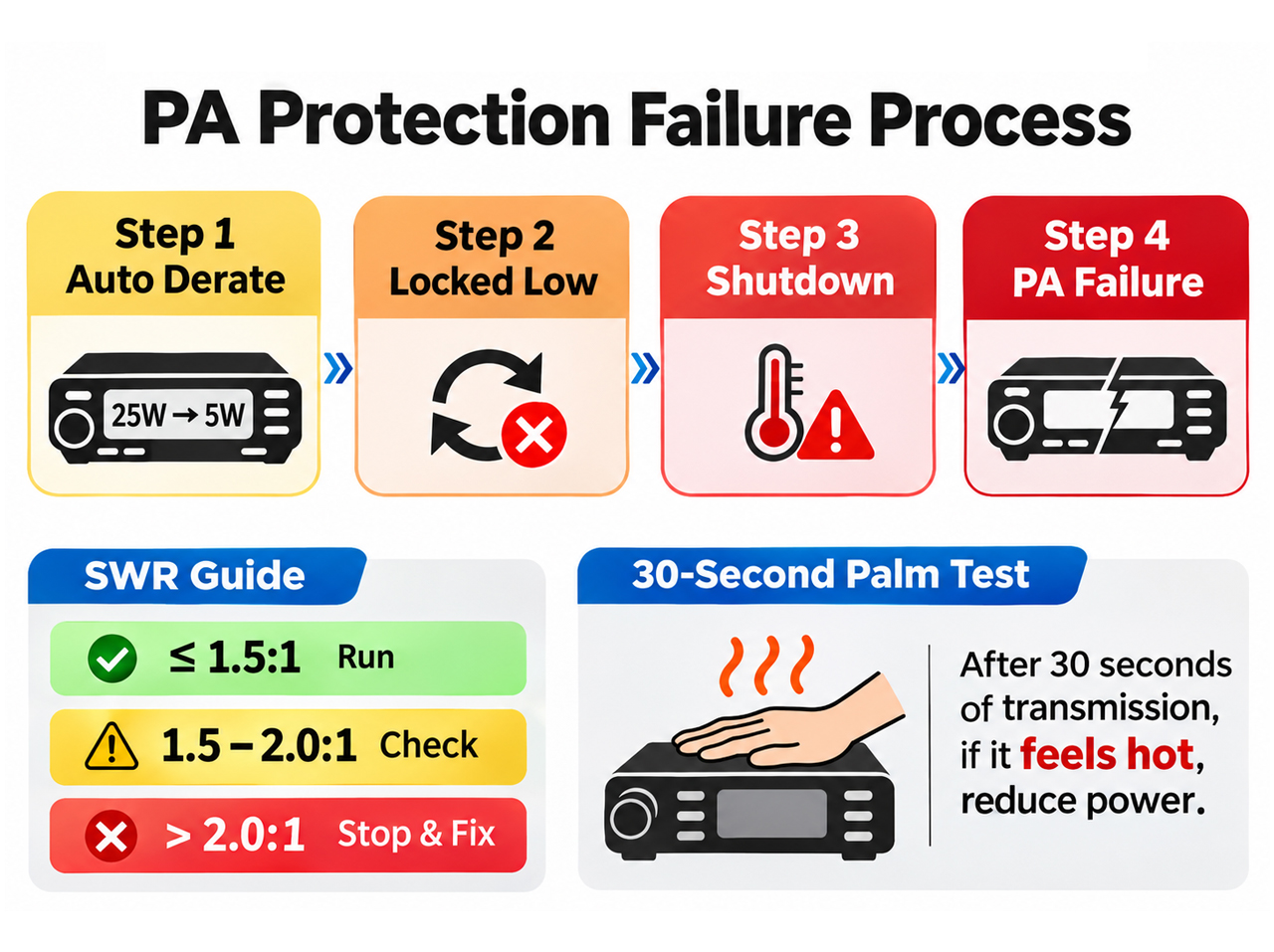
3. Re-check your SWR every six months. An SWR of 1.5:1 or better is acceptable; 1.5–2.0:1 requires investigation within the week; anything above 2.0:1 necessitates an immediate shutdown.
1. Never use temporary test cables for permanent mobile installations. Choose thin, high-temperature-resistant coaxial cable—such as LMR-400. LMR-400 exhibits only 3.0 dB loss per 100 ft at 400 MHz, and its bonded foil plus tinned copper braid prevents stray RF ingress between adjacent radio lines.
2. Connectors: Apply dielectric grease only to the outer shell, never to the center pin. Ensure the shielding is firmly compressed before tightening the flange—secure the shield first, then tighten the connector.
3. Re-check your SWR every six months. An SWR of 1.5:1 or better is acceptable; 1.5–2.0:1 requires investigation within the week; anything above 2.0:1 necessitates an immediate shutdown.
Modern power amplifiers feature dual-protection systems for temperature and SWR. If triggered, the system proceeds through four stages:
1. **Automatic Derating:** Power drops (e.g., from 25W to 5W or 1W). The unit continues to transmit and may appear normal, masking the underlying issue.
2. **Low-Power Lockout:** The unit cannot return to full power even after a restart; it requires a cooling-off period of several minutes.
3. **Complete Shutdown:** Triggered by thermal sensors, the unit ceases transmission entirely.
4. **Catastrophic Failure:** The power transistor burns out, rendering the device useless (turning it into a mere paperweight).
1. **Automatic Derating:** Power drops (e.g., from 25W to 5W or 1W). The unit continues to transmit and may appear normal, masking the underlying issue.
2. **Low-Power Lockout:** The unit cannot return to full power even after a restart; it requires a cooling-off period of several minutes.
3. **Complete Shutdown:** Triggered by thermal sensors, the unit ceases transmission entirely.
4. **Catastrophic Failure:** The power transistor burns out, rendering the device useless (turning it into a mere paperweight).
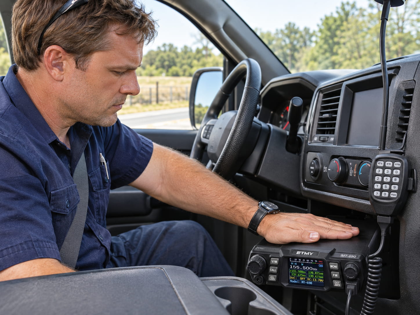
Mike is currently at the second stage; the third stage is likely just days away. A simple way to catch this early: after 30 seconds of transmission, touch the amplifier’s housing. It should be warm—that’s acceptable—but if it’s hot to the touch, that’s your final warning to reduce power.
1. EIRP Math: Calculate power plus antenna gain, minus feedline loss, and compare it against the band’s legal limit. If you exceed the limit, either reduce your power or change your antenna. There is no setting that allows those "extra" watts to magically radiate from the antenna.
2. SWR: 1.5:1 or better is safe for operation; 1.5–2.0:1 warrants investigation this week; 2.0:1 or worse means you must stop transmitting.
3. The "Hand Test": After 30 seconds of transmission, touch the amplifier housing. Warm is fine; hot is your final warning.
2. SWR: 1.5:1 or better is safe for operation; 1.5–2.0:1 warrants investigation this week; 2.0:1 or worse means you must stop transmitting.
3. The "Hand Test": After 30 seconds of transmission, touch the amplifier housing. Warm is fine; hot is your final warning.
Why Your 5W Handheld Radio Can't Hit the Mountain Repeater?
Related Article

When a 5W walkie talkie cannot reach a repeater in the mountains, the fault is rarely the transmitter. Radio-horizon math shows a waist-high antenna sees only about five kilometers, while a single mid-size hillside quietly absorbs 10 to 30 dB of signal. Adding power buys only marginal gain; climbing fifteen meters to a ridge line often unlocks what twenty watts never could. Antenna height remains the first variable; terrain, not radio, sets the ceiling.
Why Your 5W Handheld Radio Can't Hit the Mountain Repeater?

A practical guide to testing two-way radio coverage in the environment where people will actually depend on it.
Why a Radio Coverage Test Can Pass— and the System Still Fails in Real Operation

Most radio operators never take grounding seriously—until their gear is fried. This piece exposes three fatal grounding traps, from shallow rods to mixed signal-and-power grounds, then hands you a six-step, code-compliant checklist drawn from NEC Article 810 and IEEE Std 142. Copy this homework instead.
A grounding error can instantly fry your radio—Installation guide for radio system lightning protection

Professional walkie talkie earpiece guide covering how to put on, wear, and use earpieces correctly. Features brand-specific tips for Motorola, Hytera, Baofeng, and more with structural comparisons for optimal comfort and performance.
How to use walkie talkie earpiece?- The Complete Guide to Walkie Talkie Earpiece Setup